Which lathe?

Hi Gang,

I think I have an answer to the great micron mystery. One micron is
(more-or-less) 40 millionth’s of an inch. Which isn’t entirely
insane. It’s just three more digits beyond tenths. (ten thousandths
of an inch.)) I have a DTI and a digital mike that’ll read 50
millionths. (I got lost in all the zeros when I wrote it down the
first time, didn’t realize that it was ‘merely’ almost 40 millionths.
I think in inches, not metric, sorry.)

There were, back in the day, things called optical micrometers that
could hit millionths. We had them. (very rarely) I imagine the
Soviets ‘borrowed’ a few of them too. The problem is that yes, the
old optical mikes (bench mounted contraptions) and my modern gear
will give you a number. Whether or not that number means anything
is another question entirely. Steel expands 6 millionths per degree
(F). So just picking the part up, or leaving your hand on the mike
for a few seconds will trash your reading. Likewise, if there’s any
variation in the room temp, you’re off to the races, chasing a
meaningless number. The list of things that can trash the reading is
nearly infinite. Normally, if you’re after a serious measurement,
you throw out the last digit. So if I want to get a solid read on
something in ten-thousandths of an inch (.0001") I need a mike
that’ll read to .00005. AKA 50 millionths, or a smidge more than a
micron. I use the fancy mike for measuring gold foil for damascene.
Also, I have a.00005" reading DTI. I never use it because the cat
walking across the other end of the room is enough to send it
bouncing all over the place. Getting that level of measurement to
mean anything is an exercise in high-church metrology. It requires
burnt offerings, blood sacrifice, and a temperature and shock
controlled inner sanctum, along with priests of pure measurement,
schooled in the dark arts of metrology. If you’re serious about it,
you’re talking optical interferometers at that level of accuracy. (I
spoke with a buddy of mine who does this at lunch today. The
conversation quickly turned to gear that uses the spin state of
individual photons to get a distance reading. Not something that was
going to happen in Russia 40 years ago.) Just by way of example,
modern lab grade gage blocks have error bars 8/10 of a micron wide.
Meaning that they can be oversize by.2 microns, or under by.6. (for
the Starret lab master ultra precise blocks.) That’s very nearly the
best thing available anywhere on the planet, now. No way they were
machining production parts to. 001 microns 40 years ago. Sorry, just
not plausible.

What I think Leonid was talking about wasn’t surface accuracy, but
surface finish.

To bring this back to jewelry, once upon a time, when I was young
and dumb, I made a set of rolls for my rolling mill. I sent them out
to be ground after heat treating. The specs I used were that the
roller surface had to be cylindrically flat, parallel and concentric
to the journal surfaces, plus or minus 0.001". (one thousandth of an
inch. (Two orders of magnitude less than an almost micron.) But I had
them grind the surface of the rolls to a “5 micron” surface polish.
This didn’t mean that the surface was accurate to 5 microns, only
that the depth of the surface scratches was no more than 5 microns.
Think of it like polishing a piece of silver: if you have a rouge
polish on a heart pendant, you can say that you have a roughly 1
micron polish on it, but that says absolutely nothing about the
measurements of the shape of that heart. You can have a beautifully
polished piece of metal that’s totally the wrong shape.

What twigged it was when he was talking about the 10 CM ‘cube of
cubes’. That’s an old trick: Johansson did that with the first gage
blocks. They’d stick together when ‘wrung’ together. But it wasn’t a
function of the accuracy of their size, but of the quality of
their surface finish.

(Exactly why they stick together’s an interesting, and not entirely
settled discussion, but lately, suspicion has settled firmly on
gekkos. Little gekkos holding them together. (No, not really, but the
thought is that they’re sticking together mainly due to van der Waals
force, which is what helps gekkos stick to walls.))

So, that’s my theory about Leonid and the Magic Microns. Take it for
what it’s worth.

Regards,
Brian.
I have used for some years what is known over here as a "Clarke"
Lathe and a vertical miller. They are both of Chinese manufacture
and for my light “jewellery” work I have found them to be handy,
excellent and accurate. They sell here for about UKP 500 each and I
bought them from the local tool shop. Made lots of wedding rings on
them in Titanium, Gold and silver. I have a larger Myford model
makers lathe for heavy work but its not as handy and as easy to use
as the “Chinese” lathes. A friend of mine has just bought one in the
U.S. it’s not called “Clarke” over there but is the same just
rebadged. The back gears are moulded plastic which worried me in the
beginning but they never gave any trouble.

Long ago in the '80’s I was a metalwork teacher in Zimbabwe. My
students knew me as Meesta Castle. The metalwork shop had a nice
lathe except the motor was dead. I made a crank handle to turn the
headstock by hand and many students passed their exams using the
lathe with hand power.

A good lathe starts with the bed. It must be solid. Next are the
headstock bearings. Then the carriage which holds and directs the
tool. A power feed is nice, and a separate screw thread feed is
nicer.

Then all the accessories…3-jaw and 4-jaw chucks, a face plate,
tailstock centers, and the tooling.

Now I’m a jeweller turning the work by hand in a hand vice, the
tooling is a file, and the measurements are “size fitting”… a
lovely phrase from Zim when asked, “What size”?

I don’t need a lathe but it would be nice. The ancients turned
granite columns using a crank handle and chisels and they were very
good!

Alastair

You do know what a micron is? 0.00001mm is ten microns, which I
would consider more "pedestrian" than one. 

No, 0.00001 mm is 0.01 microns, not 10 microns.

First, one micrometre(micron) is 0.001 mm.

0.00001 mm is smaller than one micron, so obviously 0.00001 mm can’t
be 10 microns…

Conversion—>0.00001 mm / 0.001 mm = 0.01 microns

 You do know what a micron is? 0.00001mm is ten microns, which I
 would consider more "pedestrian" than one.
 I know that micron is 0.001 mm. Please check your sources.

Sorry, mixing meters and mm. But please tell me how you measure to
0.01 micron.

Al Balmer
Pine City, NY

There were, back in the day, things called optical micrometers
that could hit millionths. 

Yes, there are various optical methods, but as you point out, unless
measured under laboratory conditions, the measurements are
meaningless.

What I *think* Leonid was talking about wasn't surface accuracy,
but surface *finish*. 

Now, that I can believe. Since it’s relative, not absolute, surface
roughness in the micron range is easy to measure, as is flatness.
Sometimes the table of a well-polished stone will show Newton’s
rings against the lid of a glass gem container, giving a direct
measure of flatness.

Al Balmer
Pine City, NY

What I *think* Leonid was talking about wasn't surface accuracy,
but surface *finish*. 

It is always about finish. Suppose blueprint indicates delta 4, the
diameter is 6mm. It means that diameter can be from 5.9mm to 6.1. It
is also follows that there isn’t a depression less than 5.9mm and
protrusion greater than 6.1mm. So difference between highest and
lowest point of surface should not exceed 0.2mm, which translates to
a rough surface. If delta 6 is indicated than i would be 0.002mm.
That is why delta terminology is used. Sorry if you took it that I
was talking about actual dimensions of parts. I want to correct the
notion that micron is 1/40,000,000 of an inch. Micron is 10^-6 of a
meter. Meter is the standard unit of measurement in metric system and
it is slightly more than 1 yard. Micron is also 0.001 mm. 1mm
approximately 0.04 inch (slightly less), so 1 micron is 0.00004 of an
inch or 4/100000.

Leonid Surpin

First, the highest precision worked in the shop was delta 8 or
0.00001 mm, so one micron was somewhat pedestrian. You do know
what a micron is? 0.00001mm is ten microns, which I would consider
more "pedestrian" than one. 

I must be breathing too much cutting fluid, because I thought
that…

0.1 mm is 100 micron
0.010 mm is 10 micron
0.001 mm is 1 micron

so 0.00001 mm is 10 nanometer

Today I had to adjust the A-axis on the CNC mill by -0.155 whatevers,
because the tilt was off by 60 micrometers from front to back.
Spindle run out is 10 micrometer, so I won’t be getting delta 8
anytime soon.

Jeff Simkins
Microelectronics Engineer
University of Cincinnati

Sorry, mixing meters and mm. But please tell me how you measure to
0.01 micron. 

I think I explained it several times. Read previous posts

Leonid Surpin

Today I had to adjust the A-axis on the CNC mill by -0.155
whatevers, because the tilt was off by 60 micrometers from front to
back. Spindle run out is 10 micrometer, so I won't be getting delta
8 anytime soon. 

I always believed that CNC engineers are like children. One starts
their training with CNC toys and once they grow up they can be
allowed to work with real machinery.

Leonid Surpin

Hi Leonid,

To take your points not-exactly-in-order…

I want to correct the notion that micron is 1/40,000,000 of an
inch. Micron is 10^-6 of a meter. Meter is the standard unit of
measurement in metric system and it is slightly more than 1 yard.
Micron is also 0.001 mm. 1mm approximately 0.04 inch (slightly
less), so 1 micron is 0.00004 of an inch or 4/100000. 

I think you got lost in all the zeros, same as I did when this all
started. The number you list at the beginning of the quote above is
one 40 millionth of an inch.

What I was talking about yesterday was equating (roughly) one micron
to 40 millionths of an inch. Or 0.000040". Which is just exactly what
you come up with at the end of the quote above. Just to be
completely pedantic about it, it’s not 40 millionths, it’s 39.3701
millionths of an inch. (Or 0.0000373701") which is what I wrote as
the second or third word of my first post on this subject, a couple
of days ago.

Actually, a micron is .001mm. Anything else is just an approximation.
The only reason I converted into inches to start with is that I think
in inches at this scale.

(A relic of my early training. A condition you may not be familiar
with.)

What I think Leonid was talking about wasn’t surface accuracy,
but surface finish.

It is always about finish. Suppose blueprint indicates delta 4,
the diameter is 6mm. It means that diameter can be from 5.9mm to
6.1. 

No, actually it doesn’t. I don’t know about Russian prints, but on a
modern ISO print, you’d have tolerances listed, quite apart from
surface finish requirements.

There are quite a number of different symbols used, to tell the poor
bugger who’s got to make the part which types of tolerance matter. A
good reference for them is heRe:

To go back to the example of the rolling mill rolls I made in
college: when I sent them out, I specified a 5micron surface finish,
and I specified that the main rolls had to be straight, and
concentric with the journal surfaces to within .001" I also gave
them a tolerance for the diameters of the journals, and a tolerance
that indicated that the two main roll surfaces had to be within.001"
of the same diameter, but I didn’t tolerance what diameter they
had to be. It didn’t matter, so long as they were both pretty close
to identical. I also said nothing about the length of the journal
surfaces, or the length of the rolling mill main sections. I’d
already turned those to size, and they didn’t need to be messed with.
If I’d just given them only one tolerance, they’d have had to try to
get everything to within .001", which would have cost a fortune.

Returning to your example, you’ve got a callout for a 6mm diameter.
With your omnitolerance of delta 4, you’ve got error bars .2mm
apart. So is it plus nothing, minus .2? or plus .2, minus nothing? or
.1 either way? This matters a lot, depending on the nature of the
part, and the job it has to perform.

A shaft that’s.2mm oversize is a much bigger problem than one that’s.
2mm under. Equally, a bored hole .2 undersize is an entirely
different problem than one that’s .2 loose. With a ‘one-size-fits-
none’ approach to tolerances, you have no way to specify what
matters, and no way to talk about whether it’s better to be too big,
or too small on a given surface, or even whether a given surface’s
measurement really matters at all.

Further, in the surface finish realms you’ve been talking about, (>1
micron) that’s strictly a grinder game. Lathes and mills can’t get
the surfaces that fine. It’s very easy for grinders to get finely
polished surfaces on things. It’s also easy for them to make highly
polished eccentric surfaces…

So to go back to a not-entirely unreasonable mental image of a part,
lets say we have another set of rolling mill rolls. The print says
that the main roll section must be 100mm in diameter, with a
tolerance of .01mm either way. (error bars 20 microns apart) Surface
finish of 5 microns or better.

What that ends up with is a cylinder with a surface that has a very
fine surface on it, but one end of the roll could be at 100.01mm,
while the other end could be at 99.99mm, and nobody said anything
about concentricity with the journals, or actual roundness of the
part. The part could be out of round by as much as .02mm and it would
still pass inspection on the main tolerance numbers, even no
individual scratch or dent was more than .005mm deep. Grinders are
also famous for having their own guideways ground to crap. Think
about it: grinders spend their entire lives coated in abrasive gunk.
Which gets carried into their ways, and does what abrasives do best:
abrade the surfaces that the grinder moves on, slowly destroying the
machine’s accuracy. So there’s no guarantee that the grinding wheel
is even moving in a straight line, nevermind that it makes any sort
of a plane. But it can still turn out parts that’ll pass tolerance
testing, depending on how wide the error bars are set.

If you really want to get into the zen of accurate movement of
machines, take a read on Old Man Moore’s book: Foundations of
Mechanical Accuracy
.

You can get it direct from Moore machinery. (for a mere $150. Here:
http://www.ganoksin.com/gnkurl/1tq ) Moore was the guy who invented
the Moore jig borer. It was said of him that he personally added
another zero to worldwide accuracy. (Having a decimal place ‘named’
after you is pretty high praise, methinks.)

Regards,
Brian

Sorry if you took it that I was talking about actual dimensions of
parts. 

I (and apparently others) certainly took it that way.

Al Balmer
Pine City, NY

Brian,

No, actually it doesn't. I don't know about Russian prints, but on
a modern ISO print, you'd have tolerances listed, quite apart from
surface finish requirements. 

You’re absolutely correct, at least in regards to the US. We
machined all of the Honda steering knuckle assemblies for their ATV’s
(ductile iron). When they first contracted with us, their prints
were from Japan with all of the machining dimensions and tolerances
appropriately documented. However, there were no surface finish
tolerances on the print. When the first sample parts were produced,
the parts met the print requirements, but not their needs. An added
notation on the prints for finish requirements (and a price
increase) was required to satisfy their needs.

The part could be out of round by as much as .02mm and it would
still pass inspection on the main tolerance numbers, even no
individual scratch or dent was more than .005mm deep. 

That’s why for items similar to bearing bores, tolerances for
cylindricity, circularity, concentricity and surface finish all need
to be specified individually.

Jamie

I always believed that CNC engineers are like children. 

You going for the prize Leonid? :open_mouth:

If you insult enough people an award will be named after you :wink:

Your point of view is one thing, but insulting others when they
differ from your views (or when they prove you wrong)… seriously?

CNC and computer construction methods are the future of our
industry.

Commercial enterprises will go the computer route 100% (if they
haven’t already).

Eventually hand making jewellery will become a niche craft, like
blacksmithing or leather work, both of which I do.

Sure there will always be a demand for hand made items, but 95% will
be for computer designed and generated items.

It’s cheaper for the consumer also, it will become cheaper to buy a
new ring than to have one repaired.

Regards Charles A.

Actually, a micron is .001mm. Anything else is just an
approximation. The only reason I converted into inches to start
with is that I think in inches at this scale. 

It doesn’t have to be an approximation. 1 inch is exactly 25.4mm, by
definition.

Al Balmer
Pine City, NY

Charles,

I have wondered about our advancing technologies for some time. I
worry about all the people over the world who have been displaced by
technology. Have we gone too far? What is to become of all the
millions of unemployed? Maybe in the end simple was best for all,
everyone’s hands were busy. Enough contemplation, back to work.

Peace for all people,
Carole

I always believed that CNC engineers are like children. One starts
their training with CNC toys and once they grow up they can be
allowed to work with real machinery. 

Gee, that was a sloppy, inaccurate and insulting post! (I would like
to hear a moderators opinion on this one…).You have in one blow
without really thinking, disqualified many engineers around the world
and call them “children”. This type of behaviour is common when
someone does not FULLY understand,in this case a
tool/machine/workmethods, and refer to a certain piece of machinery
as a “toy”. Or because he/she simply dislikes it.

“Real machinery”? Fortunately, you’re not the one who defines what
is “real machinery”. CNC-machines are designed for high-accuracy,
high-reliability and high-productivity if you haven’t noticed that.
They are not “toys”. If you can only tolerate tools that are operated
by hand,then it’s fine for YOU.

Why not have a look at some ultra precision machining systems at
Moore Nanotechnology Systems, LLC (Nanotech[tm]) for example?
http://www.ganoksin.com/gnkurl/1tz (No toys there…)

Instead of beeing insulting you should have posted your preferences.
Not that YOUR preferences is the “only real thing”.

You have in the past said that you’re no expert on lathes “but can
find your way round one”, so why make a statement like this if you
want to be taken seriously?

Actually I did not buy my CNC setup with making jewelry in mind. I
bought it after moving near Gallup after becoming unemployed from
Honeywell Aerospace in Tucson. While sending out resumes, I thought
of attempting some contract engineering on the side for firms in
Albuquerque, 300 miles east.

I’m about as good with writing large software systems as Leonid is
with jewelry making (no idle boast - it was literally my life for
between 15 to 20 years), I’m also a fair hand with writing embedded
code, and I can build and debug simple electronics circuits and
connect them to processor boards through memory mapped I/O lines.

I thought that teaching myself how to make simple machine parts
could, in conjunction with my other skills, allow me to create
practically any apparatus. I had no illusions that I would make
perfect parts, but I figured after practice I could make decent parts
for prototypes.

The economy was so bad I that even firms in Albuquerque were not
interested in retaining a contractor for prototyping because no one
was wanting any prototypes made!

So I practiced making molds in bismuth, to make polyurethane rubber
stamps for my wife. It’s a nice, fairly forgiving way to train on a
CNC.

At the same time, I had made friends with a Dine’ master
silversmith, who showed me how to make a cast in Tufa. I discovered
that Tufa is a soft material which keeps CNC carved shapes extremely
well, making details which can be discerned from each other down
to.01 inches. I actually gave the master a Tufa mold I had machined
for my first casting.

From there I started becoming fascinated with silver. From there I
started becoming interested not in silversmithing per se, which is
a trade that applies to large items of silver, but much smaller
work (goldsmithing but using silver). 

I actually do not use my CNC to create silver jewelry directly. I
also had no further occasion to do Tufa casting yet. I use mine as a
helper of sorts, to do mundane tasks like square up stock, cut
perfect circles, make custom cutouts, and also as a precision drill
press to make wire-sized holes precisely where I want them. Oh yes,
and make wood/aluminum/steel fixtures, custom tools, and textured
bench blocks.

In other words, it does a lot of things that jewelers use jewelers
saws, sanding sticks, files, and drill presses for. But I still have
to anneal and shape stock from ingot, roll out sheet and wire, use my
butane pencil to fuse (not yet up to sterling and using pickle,
sorry, but since none of my exceeds .5 in any dimension I have the
square-cube law in my favor for structural strength of fine silver),
and use my jewelers saw and abrasives where the CNC would take more
time to set up than to get the task done. And a CNC can’t polish,
either, so I have to do that too.

So no, I’m not approaching my Taig as a toy. I might not yet be
approaching it as a full mill either, although I stretch my limits as
time goes by. My Taig is a multipurpose power tool, no more, no less.

Andrew Jonathan Fine

Sure there will always be a demand for hand made items, but 95%
will be for computer designed and generated items. 
It's cheaper for the consumer also, it will become cheaper to buy
a new ring than to have one repaired. 

If you are talking about commercial mass produced low quality
products that won’t hold up for long, you are right. For some custom
pieces, this has not been my experience. Someone who really knows
what they are doing, a person with significant bench experience will
have a greater chance of doing it right and doing it for the same
price as having someone carve a wax model. My experience is that the
price for CAD CAM and the production of the model to be cast can be
twice as expensive as a hand carved model. My opinion is that this
technology drives the market because the customer does not know that
they are paying twice as much. The customer does not get a quote for
a hand made wax and a computer generated image and a grown or milled
model to compare. I had a job and tried someone new that picked up
and delivered. They did the computer generated image which I emailed
to the customer, which was approved, the model was delivered to me,
and I had the feeling it was not quite right. I was nervous to go
ahead and took it to the person who I had had good success with in
the past. He noticed two issues. One was at the corners, there were
not enough beads to secure the diamonds. The other issue was the
height of the whole ring was not high enough, an esthetic thing, but
gave much more dimension that added a lot to the visual context,
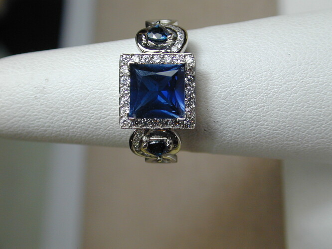
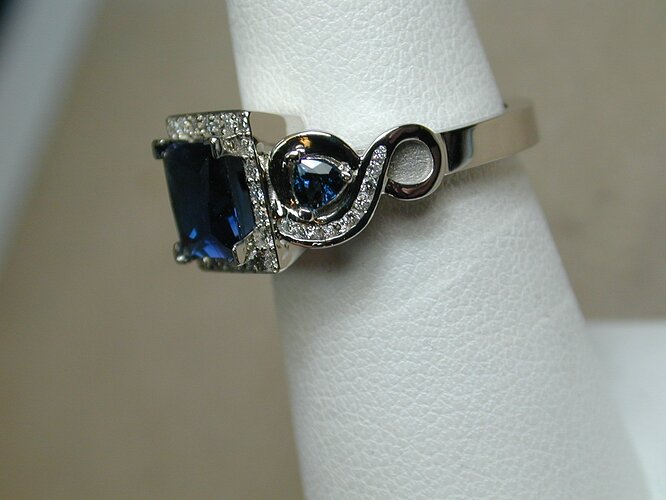
setting the 7X7 square natural sapphire a little higher off the
finger looked so much better. My opinion is that this is the problem
with those who do not have enough experience is the real world of
jewelry making and have great concepts, but mediocre execution. They
do not know what they do not know. The other issue, the first person
wanted $2000 for the CAD CAM, milling the model, casting, supplying
diamonds surrounding the sapphire, two trillion sapphires set on
either side and setting the gems. The person I had used before,
$1250. The difference partly was that the higher price included CAD
CAM and milling that was $500.


Richard Hart G.G.
Denver, Co.

Leonid,

Yeah, you seem to be going for the prize this time.

I understand where you’re coming from, as many of the CAD (as
distinct from CAM) kids that I know are idiots. Having never run a
lathe or mill by hand, they code the machines to do things that any
half-way- competent manual machinist wouldn’t ever think of doing.
But that’s a failure of training, and to a lesser extent, of the mind
running the machine, not the machine itself.

Having just gotten back into CNC work after chucking it all as “not
good enough” 20 years ago, it’s stunning what the modern multi axis
machines can do.

The things these machines are capable of will bend your head, if
you’re used to manual machines.

I do all the CNC work on the Knew Concepts lines. Just by way of
example, the big aluminum table on the power saw: Lee was doing them
by hand on a manual mill before I came along. Took him about 45
minutes to do one. I run a nicer part, with much more milling on it,
in under ten minutes. Picture being able to change tools in under 6
seconds, with a magazine of more than 20 tools queued up and ready to
go instantly, on any given job. I can switch from a 4" face mill, to a
1/2" end mill, to a roundover bit, to a drill, to a tap…in
seconds.

With the machine’s ability to interpolate axes, I can do things that
you’d never do on a manual machine. For example: those tables for
the saw. They start out as a rectangular slab of 1/2" aluminum. What
Lee was doing originally was taking a stack of 10 of them, setting
them up in the vise sideways, and running a roundover bit across one
corner of the stack, to round one corner of each table in the stack.
Then unclamping, flipping the whole stack over to the next corner,
rounding that, and so on. Took bloody forever, and when he was done,
he had an aluminum plate with rounded corners. Great, but he couldn’t
run a roundover bit along the edge of the part so that the top of the
table was rounded over too. I can, and I can also interpolate the
rounding on the corners, such that I can round all six corners of
the part, as well as running the roundover around it in such a way
that the whole thing’s rounded. In roughly a minute.

(There’s a cutout in the back that couldn’t be rounded over,
previously. Just couldn’t get a tool in there on the manual
machine.) The speeds these new machines are capable of are
terrifying. On another part, I need to remove a chunk of aluminum to
create a shoulder. 1" thick, by 2 inches wide, by about 1.5" deep.
Gone in about 45 seconds, and that’s being conservative. Try that
with a manual mill.

Better yet, google “rigid tapping”. You know the blade clamps on the
Knew Concepts saws? They’re done with forging taps, at better than
1000 RPM.

Again, try that with a “real” tool. The little baby CNC’s that get
used for jewelry, or hobby use can’t handle this sort of thing, but
the big boys can, and they’ll blow your mind.

That’s just our big vertical mill.

We just picked up a Swiss style CNC lathe. Has 5 axes. The normal
lathe axes, plus powered milling cutters from the sides and ends.
It’s even capable of milling a flat surface onto the side of a part,
while it’s rotating. (Usually, hexes, like you’d see on the end of a
bolt, but that’s not anywhere near the limit.)

The bigger cousins have 7 axes: all that, plus another spindle and
set of powered tools facing the other way, so you can work the
back of a part as well. So one side is working the front of the
part, while the other side is working the back of the last one. You
do one, then hand off to the other spindle, and just keep on going.

Watch this:

The little teeny things that look like they’re drills coming in from
the ends and sides, but they seem to stop and reverse? Those are
taps. It’s rigid tapping around the perimeter, and into the end of
the part. From the sizes, I’d guess those are 2mm taps. Looked like
about 500 RPM.

Leonid, there will always be a place and a reason for manual
machines, but for production machining, those days are over. There’s
simply no way to compete with the speed and accuracy of the new CNC
machines. It may take longer for jewelry, because much more of what
we do is one- offs, but for production lines, it’s pretty much
inevitable. Just as anyone short of VC&A, or Cartier wouldn’t think
of a production line without castings 10 years ago, 10 years from
now, CNC waxes (at least) will be just as fundamental. You can
complain and loose, or you can adapt and thrive. The choice is yours.

Regards,
Brian.