Making half-round wire

I want to use round wire to make half-round wire using my @durston rolling mill. I have 3 or 4 different sizes on the external rollers, but do not really know the process. I tried rolling 18 gauge round copper wire through the largest, then going down the sizes hoping it would simply stretch and resize the half-round diameter, but in the smallest slot, it squished out the sides creating a sharp fin and it lengthened it as expected. I had the rollers as tight as possible…

Does each size slot require a specific gauge wire to create a nicely shaped half-round wire?

Rather than trial and error I thought I check here first looking for any recommendations.

My mill is an old Durston model SK261a, possibly 25+ years old. I looked everywhere online for information on this model and even contacted Durston, but got no response. I am thrilled to have this mill, especially when it’'s in such nice shape, but I wish I had more info on it and a manual with instructions and a diagram to disassemble for deep cleaning. I also wonder if there are accessory rollers that would fit this model…

Anyway, thanks for any recommendations anyone has to offer…
Sharon B.

2 Likes

If you have any round draw plates, just fold your wire in half and pull it through successively smaller holes. The you can make whatever size half-round that you’d like and you make 2 of each to boot!

I should note that my rolling mill has the same half-round section you described and I’ve never had a great deal of success with it unless I use it for thicker half-round stock. As soon as the material is the width of that section, it flares out and creates the fins you describe. My best workaround thus far is to use wire that is narrower than the section I’m running it through. As soon as it is the same width, I don’t run it through that spot anymore as it will only flare out at the bottom.

3 Likes

Thanks Erich… I don’t have a draw plate yet, but that sounds like a good option. I’ll look on Ebay and see if I can find an inexpensive one. I’ll try again with the mill using wire better sized to each section rather than using each section to resize the wire.

1 Like

The instructions that come with a rolling mill are not overly detailed, so welcome to the trial and error club.

First, read all the archived threads about rolling half round wire, and perhaps all the threads about rolling mills.

You might want to consider a draw plate. It will maximize your possibilities.

In your current situation, maybe you should anneal the wire before using the smallest half round roller. You might also try to ease up on how much you tighten the mill, which will require you to make a few more passes, but you would be doing this in an effort to prevent creating the flanges on your wire.

Of course, you can always remove the flanges.

2 Likes

Thx Betty2,

I’m looking at draw plates now on Ebay… Happy to discover that there are several shapes to also choose from! Of course, I’ll have to use my imagination on how one would use oval and triangular wire :slight_smile: . Can you tell I’m a novice yet?

Is it imperative to purchase a higher quality draw plate vs. the more expensive tungsten type? I also have a small K&D vintage riveting block I purchased last year that I might first experiment with as it has several holes from large to very small. It’s about 3/4" thick and 1-1/2" across…

1 Like

You don’t need a tungsten plate (but they are nice. I only just got one last year. Otherwise I’ve used steel plates for 16 years). Just make sure that it is a good quality steel plate. A lot of cheap imports from India and China are rather course and can leave your wire with striations down the length of it.

3 Likes

Please read as much as possible in the archives, doing separate searches about draw plates, rolling wire and rolling mills. I promise it will not be a waste of your time. In fact, you will learn about the uses for oval and triangular wire. The oval, for example, creates the wire for a comfort fit ring …domed on both sides.

The prevailing theory around here is that you save money in the long run by not buying the less expensive tool that doesn’t last as long or doesn’t perform as well as the higher quality tool. Time wasted in frustration is a motivator to upgrade a tool.

3 Likes

I roll 8g, 10g and 12g copper and sterling round wire into HR wire all the time. I don’t expect to do it in one pass. Just as you would with sheet, take multiple passes in .25mm increments until you get what you want. There is a limit where it will flare or flash out the sides, so figure out what it is an just miss it. Experiment with copper wire first an then, as you should with all of your experiments, write down what happens so that you can look it up if you forget what works and dosn’t work. I have notes going back over thirty year that I refer to all the time. Making jewelry is fun and, for me, experimenting or R&D is a big part of it, so have some fun…Rob

2 Likes

Further to my last post, I looked at my notes and, on my Durston 130 with outboard HR rollers, 8g round wire rolls to 3.8X1.5 HR in the largest groove and 10g round wire rolls to 3X1.25 HR in the second largest groove. In both cases, the rollers were nearly closed, but not touching. There was no flaring at the edges and the rolling was one in 3 - 5 passes…Rob

2 Likes

Thank you Rob for those specifics! Provides the perfect starting point for me with the rollers and I’ll make notes of my own results. I am also interested in the draw plates, so I’ll give that method a shot also.
Thanks to all for the answers,
Sharon B.

Using your mill for making half-round wire is one option.
By the way, they are not half round but rounded if you have the same type
of extension rollers as I have.
In matter of fact, it depends which gauge you feed in and the shape the
ware has.

For making perfect half-round wire, I use round drawing plates and pull the
size I want.
I bent a wire lenghtwise and shape the end a bit where the bend is made
with a file feed.
Then I grease the wire with some drawing oil or beewax…
Next I feed it into a fitting hole of my drawing plate and start pulling.

I find this methode much easier to make perfect round wire.
The more wires you feed into a hole determine the angle of your wire.
Two wires make a flat part of 180° each, 3 wires make 120°each, 4 make 90°
each.

By this methode, you never have any issues with whatever to my opinion.

2 Likes

Another way to make half round wire is by pulling two pieces of wire through a round drawplate.

Aurora

1 Like

Hello Sharon, The traditional way to make half- round wire is this: to make 2mmx 1mm half round. begin by making two pieces of rectangular wire 2.1 x 1.1. Solder them together at one end and then pull the soldered piece thru a round draw plate until it measures the desired size. You can then cut the two pieces apart and you have it. There are faster methods but this way is very exact. Have fun. tom

2 Likes

This is strange!

I wrote my first message as answer to this question and it shows up much later then I’ve done the posting… that’s awkward.

Yesterday I sanded, polished, and aligned the rollers. Wow! What a difference… I originally wanted to completely dismantle and clean/grease all the parts, but I don’t have spring clamp pliers yet. Even so I managed to get some of the clips off; the top wheel, the handle, and the small/large gear on the right side. However I could not remove the large gear from the post, so I replaced the gear clip and cleaned as well as I could…

There was a LOT of old, dirty black grease clumped in there. I couldn’t clean it the way I wanted by soaking all greased parts in turpentine, so I sprayed with a good lubricant and got 90% of it off. Applied fresh white lithium grease. Seems to turn more smoothly and not as noisy. I’ll take it apart again once I get the correct pliers and find out how to remove the large gear.

I have some questions that I’ve not been able to answer via Google. I wish Durston had gotten back to me with requested dismantling info on this model; I tried emailing multiple times. Not overly important, but given their support reputation, I’m a little surprised. Regardless, I hope it’s OK that I’m asking here…

I believe this is a 25 year old model (SK261A); 2nd hand purchase last year and the only reference I could find online is on a Norwegian craigslist-like website; identical model number but it has rollers with square wire grooves on the main rollers. Here are a few pics; the 1st is the only one I found via a Google search and the rest are of my machine.

From Norwegian “for sale” site:

Before cleaning rollers:

After cleaning rollers:

Enough grease?

How do I remove the large gear; it is just stuck or do I need something special to pop it off?

Did I use enough grease?

Does it have reduction gears? I don’t know how to tell by looking at the gears. I suppose I could see how many turns to make a full roller rotation…

Will those fancy 1" accessory wire rollers sold on Ebay fit Durston mills?

Lastly, related to my original post… I did roll a few test pieces of wire (multiple passes) and notice that the wire appears more flat D than true half-round; is this how it’s supposed to look?

I see “aloped” answered this question… :slight_smile: Thank you also for the specific instructions, as well as those from “TomArnold.” Copied/pasted in my notes.

Thanks in advance for any comments,
Sharon B.

2 Likes

Speaking of drawplates…
I have a question about use of drawplates…
I’ve had mine a few years now and have used them for drawing wire and tubing when I saw online someone saying you put the wire in from the back side. Oops.
I have the expensive drawplates with tungsten insert and a little funnel shaped or tapered hole from the front/printed side which is the side I’ve been putting my wire/tube into and pulling from the back side.

It seemed logical to me that the taper would help ease the wire or tube through the hole, and illogical that I’d use the back side which is just the hole. Now I’m wondering which side I should be inserting the wire through to draw? Most tutorials on the web say to put the material in from the back.

thanks, Aurora

1 Like

Greetings,

To Aurora, with the tungsten drawplates: Typically the numbers and info are on the front of the plate, but the wire comes through from the rear. There’s no law about where the info is though. What determines “the wire starts on this side” is which side has the biggest funnel shaped opening. If you cut through a drawplate, the holes are funnels, and you want to go from big to little, whichever way you have to set up the plate to get that to happen.
This is especially important with carbide plates. The carbides are inserts, and they’re just pressed into the body of the plate. They’re designed to expect force in the ‘correct’ direction for drawing. If you try to go the wrong way with a carbide plate, you’ll very likely pull the insert out, which will be a big problem.
Look at the biggest hole. Under a loupe if you have to. You should be able to see which way the main body of the hole tapers. Set up the wire to go from wide to narrow.
99% of the time, that’s from the blank side, towards the side with the numbers. The idea is that way you can see the numbers while you’re pulling, which helps you keep track of which hole you were just in, and which one’s next.
By the way, the numbers may or may not mean anything. On a lot of plates, especially the older ones, they’re just '1-2-3-4-5…" to keep track of which one’s next. May have nothing to do with sizes, other than which one’s smaller than the last.

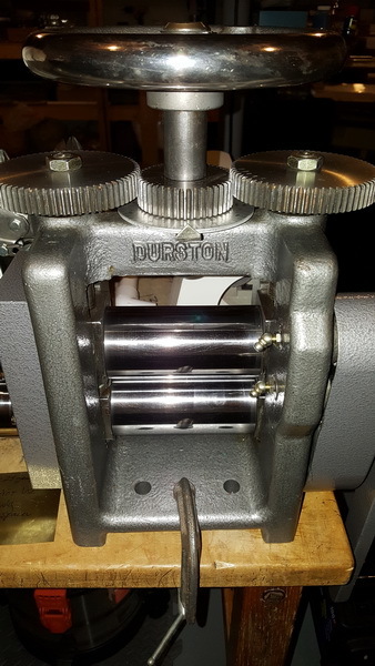
Now on to Sharon and her mill:
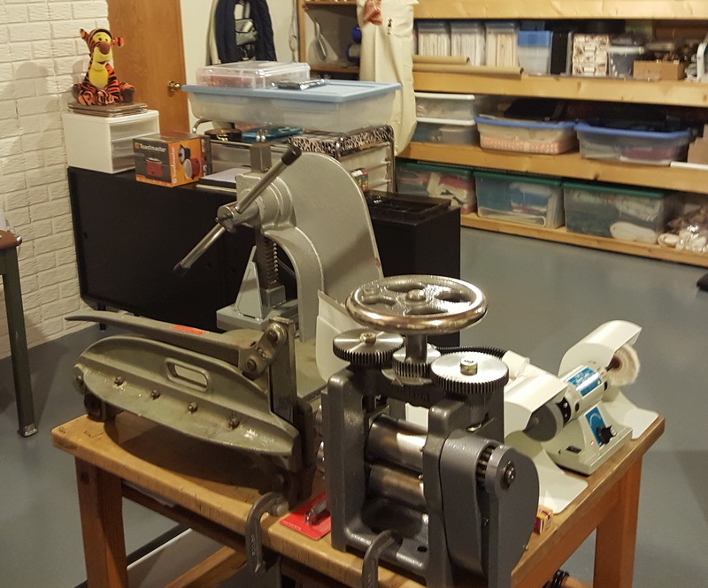
Sharon, I’m not sure you really need to pull the thing apart. I applaud the impulse to clean and spiff-ify, but unless there’s some mechanical malfunction, there’s rarely a reason to strip a mill to pieces. Cleaning off the rollers, and re-greasing the gears and guides is usually more than enough. If that shiny picture is your ‘after’, you’re done. Those rolls are clean.

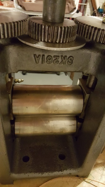
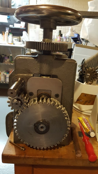
In terms of yours, yes, it’s got gear reduction, probably 4-to-1. To check, take a sharpie and put a mark on one of the rolls. Crank the handle around, and count the number of revolutions before your mark gets back to where it was. Odds are good you’ll get four cranks on the handle before it comes back around.

The big gear may need a thing called a gear puller to get it off, but it might then need an arbor press to get the gear back on. And it may not need to come off. Sometimes the bottom rolls just slide out sideways, once you get the bearing blocks out of the way. But again, I can’t think of a reason you’d need to tear the thing that far apart if it was working at all. You’ve got grease fittings on the bearing blocks, get a grease gun and shoot some white lithium grease in there. Put a bit more on the main running gears, and you should be golden.

Trust the voice of someone who’s gutted more mills than he really wanted to. Pulling the thing apart can open a very deep can of worms. Don’t go there unless you’re sure you need to. From what I can see in the pictures, you don’t.

I don’t know about the ebay rollers fitting your mill. Get a set of retaining ring pliers, pop the retaining ring off of one of the extension rollers, and pull it off sideways. Get a digital caliper, and measure the OD of the spud that the roller was sitting on, (probably metric) and also measure the thickness and height of the key on the shaft. (A square metal rod set into a groove running lengthwise on the spud.) Then compare that with whatever spec’s they give regarding the rollers on Ebay. If they match, you’re golden. Then put the roller back on.

Hope that helped,
Brian

1 Like

Brian… Thank you so much for the info. I thought it was rolling ok, but now I can tell it’s rolling much more smoothly. The large gear was also rubbing on the inside of the cover; probably got bumped and distorted the metal. I adjusted the cover while driving the screws and now it doesn’t rub, but I’ll take a closer look when I open to add more grease. I don’t think I’ll pull off the gear… Like you say, leave well enough alone.

What started this is a blog I came across where the author dismantled/restored an old Cavallin RM. He did a beautiful job on the mill and provided step by step instructions with photos. If anyone else is interested and it’s allowed, here is the website Hans Meevis Blog.

I may try a little more cleanup on the wire roller side since I will take off those rollers for measuring, but I think that’s enough. And, yes, that is my RM after cleaning the rollers. They came out very nice, didn’t they… :slight_smile: I started with 600 grit w/d paper, to 1000 grit, then Simichrome polish on a towel covered dowel rod.

Some of the Ebay listings I read for these wire rollers talk about altering the “key” on the mill… I’ll measure and hopefully find those that DO NOT require the alteration of my machine, as that is not going to happen.

One thing you recommended is to apply grease to “bearing blocks.” Are these the spots you mean?

Thank you again, Brian for taking the time to respond. It has helped greatly!
Sharon B.

Hi Sharon,

Yes, the bronze blocks that you’re pointing to are the bearings. But notice the funny little ball stalks sticking out from the right side in your picture. Those are grease fittings. (zerks). Odds are good that they lead to the proper spots for lubrication. Just get a small grease gun from the hardware store, and squirt some grease into them, and that should do it.

Failing that, heavy weight oil, or moly grease in the bearing blocks will do. (Heavy weight oil like 90wt gear oil)

Regards,
Brian

I wondered what those were :slight_smile: . I’ll get a gun and take care of it… Those “zerks” have convinced me that I WILL NOT be taking the mill completely apart now or in the future.

These should be my final RM questions. Regarding the height of the mill… Currently the centerpoint of the crank is 38.5" from the floor and when I hold my arm straight out from the shoulder, the handle when rotated to the top, fits into my hand without lowering or raising my arm. According to my understanding of at least one post (opinion) on this subject, this is the optimum height for the handle to minimize stress on the back and shoulders. Just a coincidence on my part, believe me :open_mouth: 
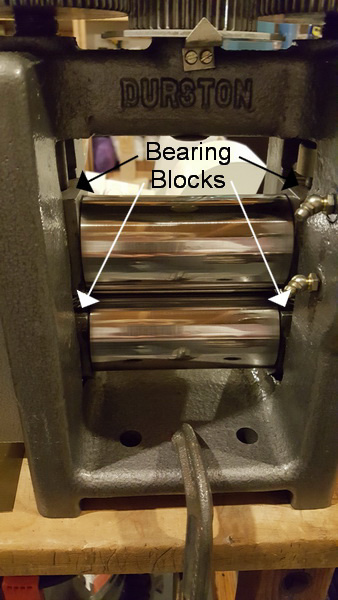
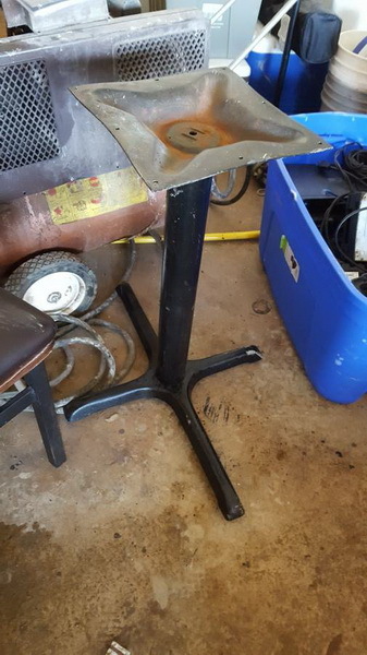
I want to be sure this is correct, as I want to move the mill to it’s own stand/table… it’s a little crowded where it is now on an old library table.

I can buy an old 29" high post base (see pic) and fit it with a double thickness of 1/2" MDF. The top plate is 11.5" square and I’d make the top 12" x 18-20". I would seat the mill centered over the post. Big question is whether the base is practical (SAFE) for a 80-100 lb rolling mill. I think it looks pretty sturdy and untippable, but if this is not a good idea, I’ll leave it where it is and move one of the other items.

Thanks again…
Sharon