Basic guidelines for jewelry design

Having worked the bench and hand carved wax for a few decades I,
like many of you, have developed a “sense” for the tolerances
required to make a design castable. Now, being a novice at CAD, I
find it difficult to translate that “feel” into precise measurements
required by CAD. It’s way too easy to get out of control with a
design that can’t be manufactured.

I have done a fairly extensive search both in these archives and
generally on the net for a basic set of guidelines for jewelry
design tolerances to serve as a base line for such things as:
minimum ring shank thickness, stone seat depth, how much extra prong
length for the setter, and a host of other issues that are the bane
of beginning CAD users.

It’s certainly true that the first requirement for a CAD student
would be a working knowledge of such things. But, as I said, in the
old-school world we tend do it by feel and experience not
necessarily by the numbers. That said, we all specialize in one way
or another. I, for instance, am really good with the metal but have
to send my items out for stone setting. You can’t know everything.

Anyway, none of the CAD apps/companies seem to provide any guidance
on this subject. Is there a resource(s) that can provide some basic
guidelines (as opposed to rules)? A cheat-sheet if you will.

Regards,
Charlie Omen
The Omen Project

Charlie

I am supposed to be on holiday through the week of July 4th, but
well I couldn’t resist replying, I have a very detailed writing on
the subject which I would love to share, but I won’t have access to
that until after next week, it’s in my office computer.

Having run a service bureau for the last 8 years, we see the
confusion day in and day out, as to the designs artists with limited
CAD experience create with CAD. I do have an extensive list of
details and of course we are always available to discuss certain
details of design here at the Bureau. Please realize I am speaking in
broad terms: yes people can cast.3 mm areas and make things so super
light that its amazing they stay together or that it cast at all, but
just some general guidelines that make it easier for all involved.
Some major fail points:

People tend to design to exact finished measurements; One of the
most critical aspects of CAD design is to allow for cleanup, I
strongly recommend adding a little bit to the desired finished
measurements, maybe one tenth of a mm to allow for cleanup

Allow enough metal for setting: add a little bit to the prong length
maybe about 1 mm from girdle to top of prong on smaller stones like 2
to 4 mm in diameter, more on larger, and less length on small stones
under 2 mm, no prongs thinner than.5 mm! we use.5 mm on micropave
prongs with a height from girdle of.65 mm.

Stone seats and settings: Designers may place drill holes under
stone seats so thin its impossible for the investment to hold up! We
see holes.3 mm (and thinner!) that are 3 mm long, this will not in
general work well at all, the investment fails and the piece has
voids in the casting from the small pieces of broken investment. Its
much better to indicate seats for stones, but don’t go deeper that
about.35 mm. Holes from about.7 mm are successful if the setting is
open up underneath the stones as well so that there is no long narrow
drill hole for the molten metal to try and swirl around.

Wall thickness: to be sure nothing is too thin so that it won’t
cast. It is very possible to design a piece that will be impossible
to mill or to grow and yet it is possible to mill and grow pieces
that still will not cast well. We suggest a minimum wall thickness for
general work of no less than.7 mm

Inset lettering: is often a problem area, people just don’t check
how amazingly thin the letters can be and they often fill in casting.
Also proper depth of letter is crucial nothing deeper than.35-.4 mm

Overall design: I can readily see when someone who has bench
experience does CAD as opposed to someone who has not worked at the
bench. A piece has to be designed so that it can be prefinished,
assembled, set and polished. Knowledge of the tools used to clean up
and finish jewelry is necessary so that the piece can be completed
successfully, just because it can be drawn doesn’t mean it can be
made into a finished piece.

Designers are responsible for their designs, they must make it
workable, not just pretty. It is the designers job to make not only a
good looking piece, but one that works through all the phases of the
process from concept to final finish. It’s not the casters fault when
a piece fails to cast if you have not properly figured the
castability of a piece, it the designers. While Service Bureas will
certainly look at your design before growing, milling or casting,
they are not the “CAD Police”. It is the height of unprofessionalism
to blame the folks who are trying to help you get your design to
fruition, when poor design skills on the designers part are the root
of the problem. So ask questions! if your not sure, Its OK, happy to
answer the most basic of questions.

Scaling: if the piece is for production, it should be scaled up
according to the process you will be using. This can be very critical
in large run pieces, consult your caster on this. We scale items for
production anywhere from 3 to 5 % depending on process, metal etc.

The best tip I can give is to place a few spheres maybe .5mm and .7mm
on your screen and move them around as guides for thickness

That said, get a good digital micrometer and measure a lot of
finished cast jewelry. Make notes on success and failure, don’t hold
a grudge when someone points out a problem with your design. Yes, you
may have to start from scratch and spend multi hours at it again, but
it’s how they show they care! And the redoing makes you better at
CAD!

Things can look very good and workable on a computer screen blown up
20 times life size and be a total fail in reality. Know you
measurements and check you measurements then check thicknesses again
before you send something off to be grown or milled.

Ill get he more detailed info to you week of the 11th

Thanks
Thomas
Cadsmithing, a Service Bureau

1 Like

the jewelers bench reference give a good list on how to judge a
design

Dear Thomas -Thank you so much for this informative and detailed
post regarding design guidelines as well as CAD recommendations.In my
years of teaching and bench work I’ve encountered so many people who
had lofty expectations about what they called “incredible and unique
designs” in their minds, yet when they were rendered, discussed and
critiqued, and then were told about the flaws… it was evident that
a lack of experience with hand’s-on execution was a major stumbling
block. Why can’t they understand function? Why don’t they learn
the definition of conceptualize? How can they become designers if
they do not understand composition, and that components are the parts
and pieces that need to be described for a design to be understood
with clarity? And, if a “designer” does not comprehend the terms and
definitions of design (I was told not to use the word nomenclature)
then how can they communicate about it with other jewelers?
Terminology is how we get to the bottom of design, yes? I don’t know
it all but I hope that after twenty five years I can advise newbies
to please learn the language of the industry, then listen closely to
guys like you, Thomas!

Many Thanks for your input.
Margie Mersky
mmwaxmodels.com

I have just retired from medicine. If you don’t know the nomenclature
(terminology) you can’t treat patients. Same is true in my new
profession. you must know the correct spelling also.

John
Rasmussen Gems & Jewelry LLC

Hi Margie,

Why can't they understand *function*? 

Because they’ve never had to. Function is something people think
they know about.

If they’ve never made a physical item, how can they understand about
function?

You need practical knowledge of construction techniques, you also
need to know your materials, and for wearable items, what is and what
isn’t comfortable.

These concepts are pretty much a given for anyone on this list, but
go to someone inexperienced, and it’s a different story.

Regards Charles A.

Know you measurements and check you measurements then check
thicknesses again before you send something off to be grown or
milled. 

Thank you Thomas, that list would be most helpful. Deeply
appreciated.

Regards,
Charlie Omen

people -

there’s way too much ‘blue sky’ areas in some jewelry designs. ‘blue
sky’ sort of translates into: “gee, i don’t know how to get to the
results i want without glossing over some intermediate sections.”

just having a vague idea for accomplishing a design isn’t going to
work if you don’t have a map establishing every step of the effort;
even the illustrations of a so-called ‘top jewelry designer’ are not
detailed enough to provide guidance on how to ‘hard copy’ the
design; the renderings are vague - the settings just trail off into
’blue sky’.

the first part of nailing down a design is looking at it from all
sides - literally. sketch the basic idea, say for a ring,
isometrically - as if it’s on an invisible finger showing an angled
setting and shank. then a side view and a front-head-on view with
parallel horizontal lines with measurements coming from the top of
setting and the bottom of the shank, with lines and measurements from
every feature between - that’s dimensioning, they will give you a
rough idea of whether the design looks feasible/doable. next an
overhead view showing the setting as if you’re looking down at it on
your finger - also with dimension lines as to stone size,
location,width, etc.

now for the nitty-gritty: sit there with paper (tracing), pencil
(mechanical .3mm/.5mm lead) and eraser, and figure just how - or if -
you can do it: - are your solder skills enough? - bezel? - prongs? -
gypsy? - side stones? - width/thickness of shank? - stone size?
(measure selected stone and remember that a lot of imported stones
are cut deeper and require more depth of bezels and prongs) -
critical point: can the design be worn with comfort?

thinking of a ‘really great design’ is the beginning of a process
with procedures you can, or cannot, accomplish - to be successful, be
honest.

good luck -
ive
dimensioning saves time - and brain cells.

While I’ll admit to not following this discussion, Ive makes some
excellent points.

Teaching what goes into a successful jewelry design is difficult at
best.

However, it is certainly useful to understand what it is you’re
attempting to make in 3 dimension. If you are uncomfortable with
using paper and pencil to draft out the different views of what you
want to create, then I would urge you to spend more time sketching,
even just making lines on the paper. A top, side, and end view at the
correct scale is a fantastic idea, and does help one understand how
the design works in space. Just one sketch of the proposed design
however artistically it might be rendered, just doesn’t give the
details necessary to actually built the design. A good series of
drawings will allow one to actually make accurate measurements of the
different parts of the design, and avoid proposed designs which won’t
actually work in the real world. Experience and practice makes the
difference in being able to take ideas into finished jewelry, and a
big part of that is being organized enough to plan how all the
components of a design really come together to form a beautiful
piece.

Digital calipers are now quite reasonably priced, and no metalsmith
should be without one, in my opinion. Being able to measure the
inside, outside, and depth of something to 1/100th of a millimeter is
pretty vital to accurate small scale work.

Jay Whaley

Ive, that’s excellent advice. It is also a pain in the neck, just
like all project planning! Basically you are on a fact-finding
mission with paper and pencil. For those who have trouble doing a 3D
design on paper, you can always build a prototype out of copper or
even clay, like FIMO. And I would add that a critical piece of the
dreaded planning is “order of operations” - this is planning out the
order of the steps so that you do not solder yourself into a corner
for example. Who of us has not done that?!

Mary Barker

Design for Casting, not for Failure.

Having run a service bureau for the last 8 years, we see the
confusion day in and day out, as to the designs artists with limited
CAD experience create with CAD. I do have an extensive list of
details and of course we are always available to discuss certain
details of design here at the Bureau.

Please realize I am speaking in broad terms: yes people can cast.3
mm areas and make things so super light that it?s amazing they stay
together, or that it cast at all, but just some general guidelines
that make it easier for all involved.

There are certain limitations when designing items for casting. In a
hand carved wax it is virtually impossible to make the minute cuts,
drill holes and voids possible that can cause casting difficulties.
with CAD and Prototyping its easy to design yourself into a corner
and make a piece that on a computer screen looks good, but in
reality is not possible to cast… The designer must be aware of the
limitations of CAD-CAM technology as well as its advantages.

The advantages such as vastly increased productivity, ease of
mirroring, scaling and repeating parts as well as the ability to
create your virtual inventory and document and be able to recreate a
piece exactly as before for production or replacement make the
initial costs and learning curve well worth it.

The learning curve can be frustrating, and it takes time and
dedication. It is also highly recommended that you plan on taking
formal training as well, it is necessary to get fully acquainted
with the software you are using. Learning CAD is much cheaper than
hiring another employee and is essential in today?s competitive
jewelry environment.

The main software we see people using for jewelry design are Matrix,
Artcam, Rhino and its plug in programs( rhino gold) and 3design.
There are several other smaller design programs that we have not
tried or are very familiar with such as monarch, firestorm and older
programs such as jewelcad and jewelspace.

There are other non jewelry specific software that are usable for
jewelry such as Maya, or Google sketchup.

The main feature of any software is that it must be able to output
an.stl file this is the usual file format that is used most standard
in the jewelry industry. The.stl file contains all the 3 dimensional
that a service bureau needs to grow or mill your piece.

Some growers may require a slc file to fit the input requirements of
their particular machine.

There are two main ways to build the models you have drawn in a CAD
program. Milling and Growing. I will discuss briefly the parameters
and limitations of milling and go into great detail on Growing
(prototyping) as that is the area where we see the most problems.

Milling. Milling has its built in limitations as well. Undercuts and
hollows will in general not be built… Milling has some great
advantages, as the taper of the tool will simply not be able to cut
most areas that are too small, or too deep to cast.

A piece that will be milled may be designed in several pieces to
achieve an over all very satisfactory item. Parts can be under cut
with further milling steps and there are some mills that can achieve
some undercutting and hollowing on pieces without additional steps.
Gemvision has a dual spindle mill that can achieve quite of bit of
undercutting. The advent of 5 axis milling will greatly increase the
ability to more completely mill a design without additional milling
steps, Artisan CNC is working in this area of 5 axis milling specific
to the jewelry industry

Advantage great surface finish, Disadvantage: not always fully true
to dimensions, can usually only mill one a just a few pieces at once.
Additional hand work is required to remove supports that were
necessary to hold work to be milled.

Growing or Prototyping will build the model exactly as the designer
draws it in the computer with limitations of build ability that
varies by type of prototyping equipment. Minimum feature size is
usually stated on the specs of each type of machine. Primary machines
used for growing are Perfactory( several models) from envisionTEC,
R66, T76 from Solidscape, Inc, and the projet MJM 3d printers from 3D
systems. All have their advantages and disadvantages, all have
fairly high operating costs.

Remember that there are certain limitations when designing a piece
to be cast and many factors have to be taken into consideration. Keep
in mind these pointers when designing a piece for casting. These are
the general guidelines we use and instruct our staff with in design
practices.

Design with cleanup in mind. Remember that your piece will have to
be cast and then filed sanded, tumbled and polish. You must allow for
that initial removal of metal. If you need a shank to be 2 mm wide
as a finished piece ad a little to the thickness to allow for
cleanup, otherwise the piece will come out thinner than planned
after finishing. We add from 0.1 to0.2 mm thickness overall to areas
that will be cleaned up.

Basic Idea to get into your head as you design When a piece is cast,
very hot metal at a high force is pushed into a confined space.
Small freestanding, unsupported areas of investment very easily shear
off and become inclusions (voids) in your casting. Think of support
for your investment wherever there is a small space. Don’t drill a.5
mm hole 2 mm long through a shank and expect it to cast
successfully.

Don’t leave little triangle voids where a circular under gallery
meets a channel

Sharp edges and corners and pieces that taper to infinity will
create problems in the build and in casting. Try to fill in little
(under.3 mm) areas with solids. Fillet sharp corners and tapers at
least .2 to .3 mm for a much better model.

Some areas of Concern:

Beads: They look great on your rendering and on the computer screen,
but with casting and cleanup they often don’t come out very well.
Larger beads are much more successful.

.5 minimum

Milgrain: Milgrain in the CAD model is generally not a good idea.
The best you will be able to cast in place is ?faux milgrain. It
really wont be milgrain and it wont look anything near as good as a
properly hand applied milgrain. It is much better for the jeweler to
roll the milgrain as a final step in the finishing of a piece. The
designer should prepare the edge for milgrain I like to use a.3 mm
wide edge that tapers thicker to the stone area it surrounds.

If you must have faux milgrain then a line of beads on edge at
least .5 minimum Can work, leave little space between the bead like .1
at least.

Drill holes: In general it is not advisable to cast in drill holes
unless they are of a size that can survive the force of metal as it
flows into the casting. Better to indicate holes in the model and
drill through in the cast metal.

Through holes no greater than 1 mm unless diameter of hole is greater
than .7 mm. Larger diameters can be longer thru lengths. Do not
create deep partially drilled hole in a piece they will usually break
off and cause small to large voids in the casting. Depth of
unsupported holes no greater than .35 mm depth.

Logos, Initials cut outs etc.: Depth no deeper than.4 mm

Diameter need to be at least .5 to be successful.

Lager designs can be deeper than this.

Designing to exact Measurements: People tend to design to exact
finished measurements; one of the most critical aspects of CAD design
is to allow for cleanup, I strongly recommend adding a little bit to
the desired finished measurements, maybe one tenth to two tenths of a
mm to allow for cleanup. Then in finishing the piece will be brought
to exact dimensions.

Ring size: make the ring just a tab smaller than finished size maybe
1/8th size small to allow for cleanup. Some people make it size
smaller. Depends on your cleanup methods and design of piece.

Allow enough metal for setting: add a little bit to the prong length
maybe about 1 mm from girdle to top of prong on smaller stones like
2 to 4 mm in diameter, more on larger, and less length on small
stones under 2 mm, no prongs thinner than .5 mm! we use .5 mm on
micropave prongs with a height from girdle of .65 mm.

Stone seats and settings: Designers may place drill holes under
stone seats so thin its impossible for the investment to hold up!

Drill holes: In general it is not advisable to cast in drill holes
unless they are of a size that can survive the force of metal as it
flows into the casting. Better to indicate holes in the model and
drill through in the cast metal.

Through holes no greater than 1 mm unless diameter of hole is
greater than .7 mm. Larger diameters can be longer thru lengths.

Do not create deep partially drilled hole in a piece they will
usually break off and cause small to large voids in the casting.
Depth of unsupported holes no greater than .35 mm depth.

Too small drill holes: We see holes .3 mm (and thinner!) that are 3
mm long, this will not in general work well at all, the investment
fails and the piece has voids in the casting from the small pieces of
broken investment. Its much better to indicate seats for stones, but
don’t go deeper that about .35 mm. Holes from about .7 mm are
successful if the setting is open up underneath the stones as well
so that there is no long narrow drill hole for the molten metal to
try and swirl around.

Wall thickness: to be sure nothing is too thin so that it won’t
cast. It is very possible to design a piece that will be impossible
to mill or to grow and yet it is possible to mill and grow pieces
that still will not cast well.

We suggest a minimum wall thickness for general work of no less
than .7 mm Wall thickness

Smaller pieces no thinner than .7 mm

Larger pieces no thinner than 1 mm

Lettering: Lettering is a tricky animal. What looks good on the
screen is many cases too small to grow and if it does successfully
grow, too narrow to be castable.

Lettering on the inside of a ring is almost always unsuccessful. If
absolutely necessary, the text should be a block style font or
similar uniform thickness font, no more than .3mm depth and no less
than .5-.7 across at the narrowest part of each letter.

Inset lettering: is often a problem area, people just don’t check how
amazingly thin the letters can be and they often fill in casting. We
routinely see letters .1 to .2 in width, which just won’t work. Also
proper depth of letter is crucial nothing deeper than .35-.4 mm

Scaling: if the piece is for production, it should be scaled up
according to the process you will be using. This can be very critical
in large run pieces, consult your caster on this. We scale items for
production anywhere from 3 to 5 % depending on process, metal etc.
let the Bureau know if something is scaled or needs to be scaled,
they will only do what you request, so make sure of this point.

Overall design: I can readily see when someone who has bench
experience does CAD as opposed to someone who has not worked at the
bench. A piece has to be designed so that it can be prefinished,
assembled, set and polished. Knowledge of the tools used to clean up
and finish jewelry is necessary so that the piece can be completed
successfully, just because it can be drawn doesn’t mean it can be
made into a finished piece.

Design Responsibility

Designers are responsible for their designs; they must make it
workable, not just pretty. It is the designer’s job to make not only
a good looking piece, but one that works through all the phases of
the process from concept to final finish. It’s not the casters fault
when a piece fails to cast if you have not properly figured the
castability of a piece, it the designers.

While Service Bureaus will certainly look at your design before
growing, milling or casting, they are not the “CAD Police”. It is the
height of unprofessionalism to blame the folks who are trying to
help you get your design to fruition, when poor design skills on the
designer?s part are the root of the problem. So ask questions! If
your not sure, Its OK, most are happy to answer the most basic of
questions.

That said, get a good digital micrometer and measure a lot of
finished cast jewelry. Make notes on success and failure; don’t hold
a grudge when someone points out a problem with your design. Yes,
you may have to start from scratch and spend multi hours at it again,
but it’s how they show they care! And the redoing makes you better
at CAD!

Things can look very good and workable on a computer screen blown up
20 times life size and be a total fail in reality. Know you
measurements and check you measurements then check thicknesses again
before you send something off to be grown or milled.

The best tip I can give is to place a few spheres maybe .5mm and
.7mm on your screen and move them around as guides for thickness.
This is your visual size reference and can help quite a bit
especially when fairly new to CAD.

If I can draw it, it will work is the motto for newbies and amateurs,
I draw it to work is the motto of the professional.

END

Copyright 2010, 2011 Thomas Cavagnaro. Cadsmithing LLC No portion of this
work in whole or part may be reproduced without the express written
permission of the author. All rights reserved.
1 Like

Hi! This is very informative. I’m wondering, are these “rules” for cad design inclusive of the casting stage or only speaking for the 3d printing process? Would casting parameters be more strict? Thanks!

I must admit that as a retired Systems Engineer and now a jewelry hobbiest I’m fascinated with with the discussion on Function. @charlesian2000 and @M_Mersky in virtually every field of design for construction the cardinal rule is FORM follows FUNCTION. Your advice offered follows the rule.
Regards RLW

Ron,
With jewelry design, form does not always
follow function.
Some jewelry used to convey an idea or a
concept rather than used as a practice
adornment or as an accessory.
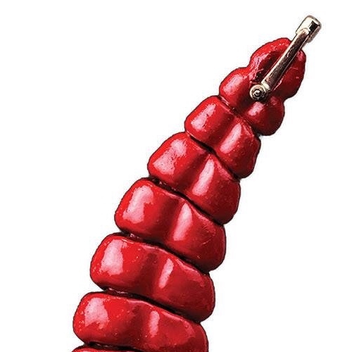
I believe this piece by Andy Cooperman
is an example.
What do you think?[image1.jpeg]

In order to view the whole image of the
picture I sent, click on the partial image
and it will open in another window.
And I meant practical, not practice.

Before shifting into jewelry 8 years ago, I used to do “jewelry for buildings”, or “steel lace for architecture”. A attorney friend when critiquing a very early commission in architectural metals (that won a national award from NOMMA), quipped looking at my finished work: “function is tertiary to design”. I was flattered by his observation. If something is gorgeous AND it is finely functional with comfort, durability, aesthetics, manufactureability in the whole ball of wax, then it’s a successful piece. You see beauty first and then appreciate it’s totality. I still hold his comment as a standard for any design /fab work, twenty years later on a much smaller scale.
Eileen

Richard_Hart3
February 4 |

In order to view the whole image of the
picture I sent, click on the partial image
and it will open in another window.
And I meant practical, not practice.

Visit Topic or reply to this email to respond.
Brought to you by:

You are receiving this because you enabled mailing list mode.

To unsubscribe from these emails, click here.

1 Like

Hi Eileen,
If its not a trade secret! just a quickie,
Can you tell ,me, in particular,

  1. Is it made from steel?
  2. 1/2in sq rod?
  3. All cut by hand? or maybe a chop saw?
  4. Tapers forged?
  5. joints arc? gas? mig? or tig? welded?
  6. Finish? shot blasted? zinc sprayed? painted?
    powder coated?
    I do a lot of metalwork of all kinds, s/steel, bronze and titanium as qwell as silver, both in jewelley and larger objects.
    Or you were primarily the designer, had it made and intalled by others?
    Very nice work, you shurely have to know metalworking to do this yourself! If so your a v/good iron smith. I know Albert Payley’s work, especially his ships capstan twisted steel!!
    Ted
    Dorset
    UK.

Ted,
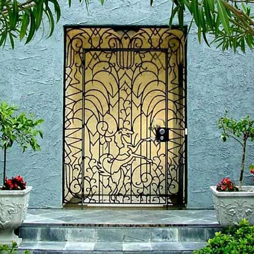
I too, am a admirer of Albert Paley. The award I received in 2000 for the borzoi gate was for a category of 10%or less forgework (steel). Paley received an award for the stainless steel (fabrication) doors that he created for the federal court building in San Francisco. I was then, and still am, in awe to be in such esteemed company.
In response to your questions - with a bit of perspective. I’m self taught at metalwork, big and small. Instead of approaching it from the old school set of tools (forge and hammer), I got practical reasons explored and exploited new engineering technologies - a tool is a technology and a technology is a tool, it’s truly under control of the artist.

  1. the gate is made from A-36 alloy mild steel PLATE (3) 4×8 sheets.
  2. The appearance is 1/2" square rod. It’s cut that way. Instead of forging, it’s complex subtractive elements cut from the sheet of plate, about 70% scrap. The remaining visual laced network of steel is composed of remaining “square rod”, all 1/2" × 1/2".
  3. it was laser cut in a Mitsubishi lxp 4030 nitrogen assist laser (as i recall). There are three 4×8 sheets of plate. The frame components are 1 1/2" wide with slightly over tolerance (+.06") square holes. The twelve frame parts took up one piece of plate. The main center design panel is a single piece of plate. The fingers of design ended up like spider legs that tenon precisely into the slotted frame. The surrounding design is four pieces that join together with three welds. They took up the third piece of plate.
    What you are looking at is 7800 linear cut inches and 238 tool paths. All of the tool paths were set in layers of sequential programming nests. Basically, every third to fourth part was cut from the plate, skipping across from left to right. Then the same thing happened again and again. The reason was to prevent the plate from overheating and coining. The plate remained flat, keeping the alignment of the mating fingers to the slots.
  4. the tapers are designed and cut as such (drawn). No forgework.
  5. TIG, & all of the welds are fill welds on the outside of the frame, ground smooth and polished. There are three panel welds, created with arrow v inset into a matching v shape with a small round void at the tip (more connecting weld surface).
  6. the steel was P&O. I washed the steel, and then applied saline spray to build up a decent, even oxidation. Then applied OSPHO to convert the oxidation to a phosphate coating. It’s quite a nice, dark charcoal color. Instead of paint, I use gilsonite asphaltum -a light tar varnish. It’s the same steel finish used on Henry Ford’s Model T (“you can have it in any color, as long as it’s black”). It allows clients to easily maintain the metal without outsourcing to a speciality paint or finish company. Though it’s great for thin metal, powder coating thick steel is an absurdity. Unless the steel is heated to 400F all the way to it’s core (& laser temp tested), the catalyzing of powder coat won’t happen. If done right, it is good for 10 years. If not, it’s an aweful mess in less than 2. If something is designed to last for a century or more, a serviceable finish makes more sense.
    The only thing you didn’t ask about was the handles, which are #316 stainless steel in 1/2" & 1". The metal was mirror polished and then water jet cut.
    I designed the project to the requested motifs of the client: ‘what’s your favorite animal’?(a Russian wolfhound), and then, ‘is there anything else you’d like’? (palms, lotus, lightning bolts and chevrons). I did the site survey and measurements. Then with that, I sat down to design the whole thing and integrate the elements into raging art deco. All of the files were created and then walked thru an older stable version of autocad to have flawless .dxf files with native arc and radius geometry (no splines or tiny line segments. I printed out a full size plot pattern for signoff approval with the client.
    Then i went shopping for who was hungriest for machine time costs (8 jobshops). If you do your own files, you can walk into any cutter, anywhere and cut for the best costs (and pass savings among). The ability to program allows to be flexible with materials, time and make whatever you’re creative self can imagine into perfection. I’m thrilled that you thought “hand craft”. It’s digital artisan blacksmithing. A dxf file is just another hammer v 100.0.
    The assembly and install took 8 hours. 3 hours of that was assembly in the shop discovering how the parts only fit one way, a bit like LEGGOES and furniture joinery. I showed up and it was already together. My guy had a smile that wrapped over he ears. I do weld, but there are lots of talented welders. I share the fun and pick my battles.
    My favorite part is the door is 125lbs and moves like a cloud. It can be easily moved with the touch of two fingers.
    Upper body strength is above the waist: in the shoulders and forearms OR between the ears. If your eyes are glazing over, my apologies, but you inquired.
    Eileen

vladimirfrater
February 4 |

Hi Eileen,
If its not a trade secret! just a quickie,
Can you tell ,me, in particular,

  • Is it made from steel?
  • 1/2in sq rod?
  • All cut by hand? or maybe a chop saw?
  • Tapers forged?
  • joints arc? gas? mig? or tig? welded?
  • Finish? shot blasted? zinc sprayed? painted?
    powder coated?
    I do a lot of metalwork of all kinds, s/steel, bronze and titanium as qwell as silver, both in jewelley and larger objects.
    Or you were primarily the designer, had it made and intalled by others?
    Very nice work, you shurely have to know metalworking to do this yourself! If so your a v/good iron smith. I know Albert Payley’s work, especially his ships capstan twisted steel!!
    Ted
    Dorset
    UK.

Visit Topic or reply to this email to respond.
Brought to you by:

You are receiving this because you enabled mailing list mode.

To unsubscribe from these emails, click here.

@Richard_Hart3 I think the thought process has gone astray. Here is an example I can agree with where workable is closely related to functionality.

In the pic you posted there was a display function that had to be met and the form played an important role in the success. In reality the object under scrutiny could have been artistic in other forms and still satisfied the the display capability.

Later in the thread there is an artistic element to a door. The primary function is to create an opening and an additional function of visually pleasing. The designer achieved both, IMHO
Regards RLW

Hi Eileen,
Well! thanks
for such a full description of your gate making project.
It all starts in ones head,ive found.
Also, I should have guessed, laser profiling, is the way to go for such intricate designs.
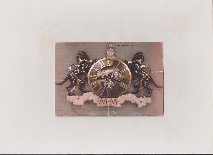
I too used it for making the millenium clock project (yr 2000) for a livery Co in the city of London, UK.
Heres I regret a poor pic of it. Cant find the file just now.
The center clock face is some 14in in dia, and laser profiled out of s/steel for stability reasons and was then gold plated along with the leopard neck chains . the plating alone was over $1000.00
Leopards carved in lime wood, salts and crest cast aluminium, and the MM in s/steel as well, clock hands in titanium. The base is rock salt which i carved! quite soft in fact, and it came from the Isralei Dead sea salt pans.


Overall width some 4ft 6in , and it was all digitised one for one off the drawings to a dxf files on an a1 digitiser. Weight around 75lbs.
Not the biggest project, that was my house I built myself in 1972. In it still!.
have you done any house building?
I wouldnt be surprised.
Ted.