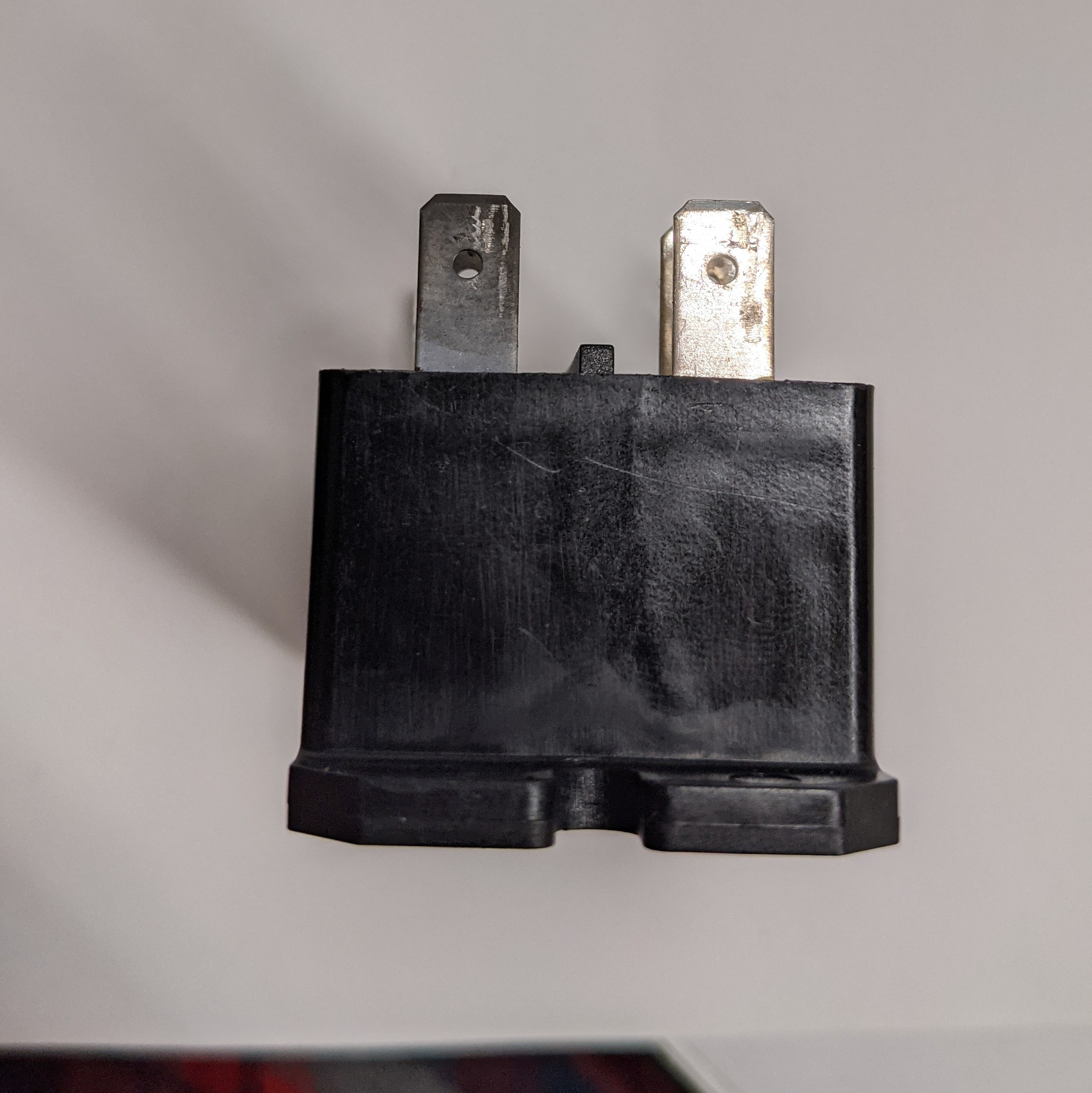
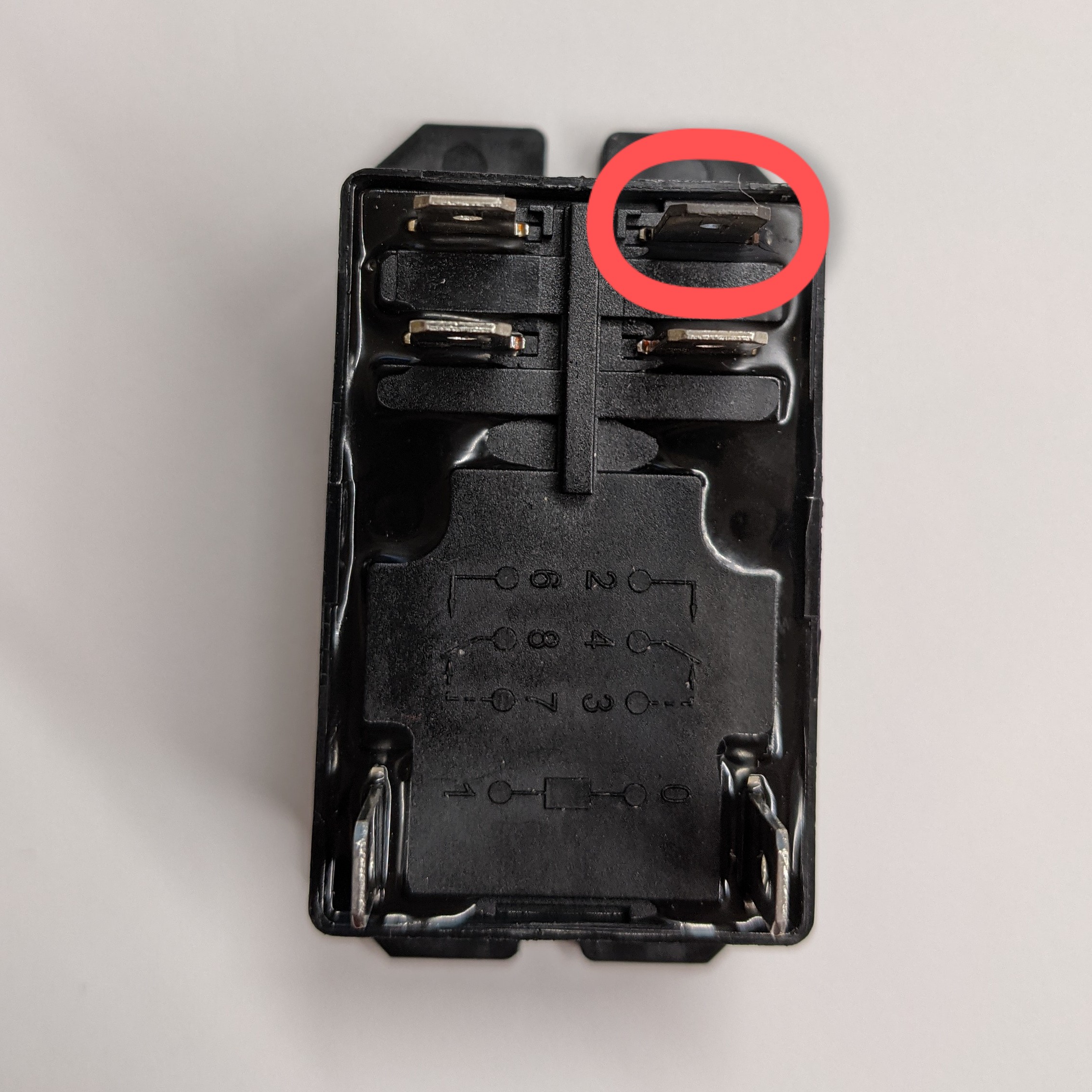
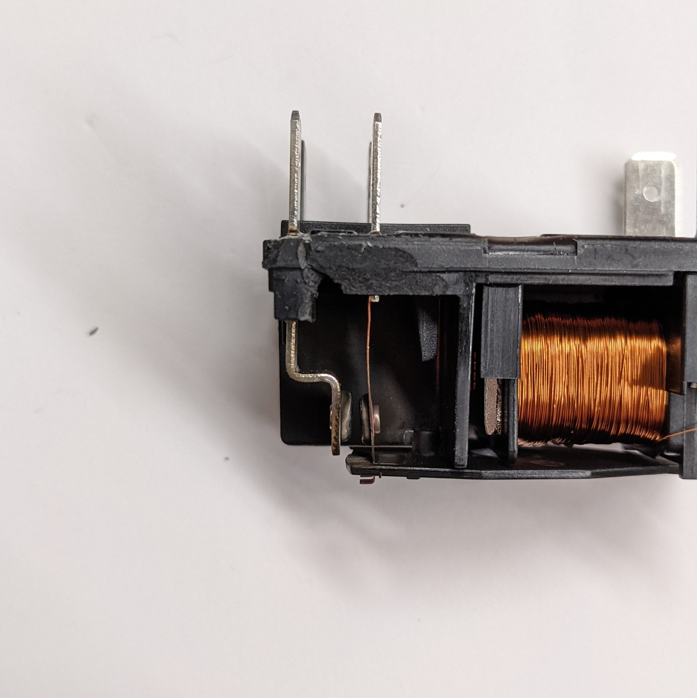
We’ve been going through a dilemma where we’ve been blowing relays at least once a month in our Paragon XL kiln (RG18-1). The location of the failure is always the same, the #2 terminal on the relay. See pictures below. This is the terminal that sends power to the elements.
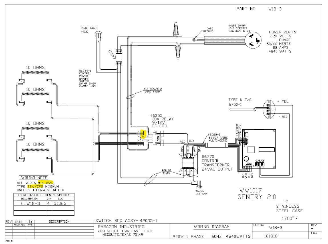
We’ve changed the wiring for all the elements, making sure it’s 14 AWG high temp wire (as noted in wiring diagram), changed all the connectors and made sure they are incredibly tight on the terminal. We’ve also insulated all the connectors to make sure no contact is made between them. We’ve checked the amperage going from the outlet into the kiln and it’s at the right level. We’ve had no other failures or issues with any other components of the kiln.
A little info on our burnout cycle, we go through a 15 hour burnout and typically hold at the casting temp for 3-4 hours before casting (start burnout at EOD 5pm and cast next morning 9pm). When the relay fails we get a Low Temp Deviation Error (LTDE) on our control unit. The point in the burnout when the failure happens is inconsistent; 1000F, 1350F and even at 350F. We run a burnout 3-5 times a week (5 days a week right now do to holiday surge).
We’re frustrated and are considering switching to a mercury or solid state relay, but I really want to figure this out because it is a problem and don’t want it potentially spreading from my relay to another part of the kiln. Is it because our relay just switches on and off too frequently and it really is just going through the lifespan of the relay in the span of a month? I’m trying to think outside the box on this, but in the back of my mind I feel like the solution is most likely a simple one.
Please let me know if anyone has any suggestions or has dealt with this in any way. Even if I’ve checked on something before, I’ll check it again, so please let me know. Thanks everyone.
Contact Arnold Howard at Paragon or any of their techs. They are very good at helping with problems with their kilns. Really! Or you can reach Arnold on Facebook. He KNOWS Paragons kilns!!!
Arnold may not still be at Paragon, but he knows kilns and kilns wiring and kilns everything. Check him out on facebook (I know it’s facebook, but still. . . ).
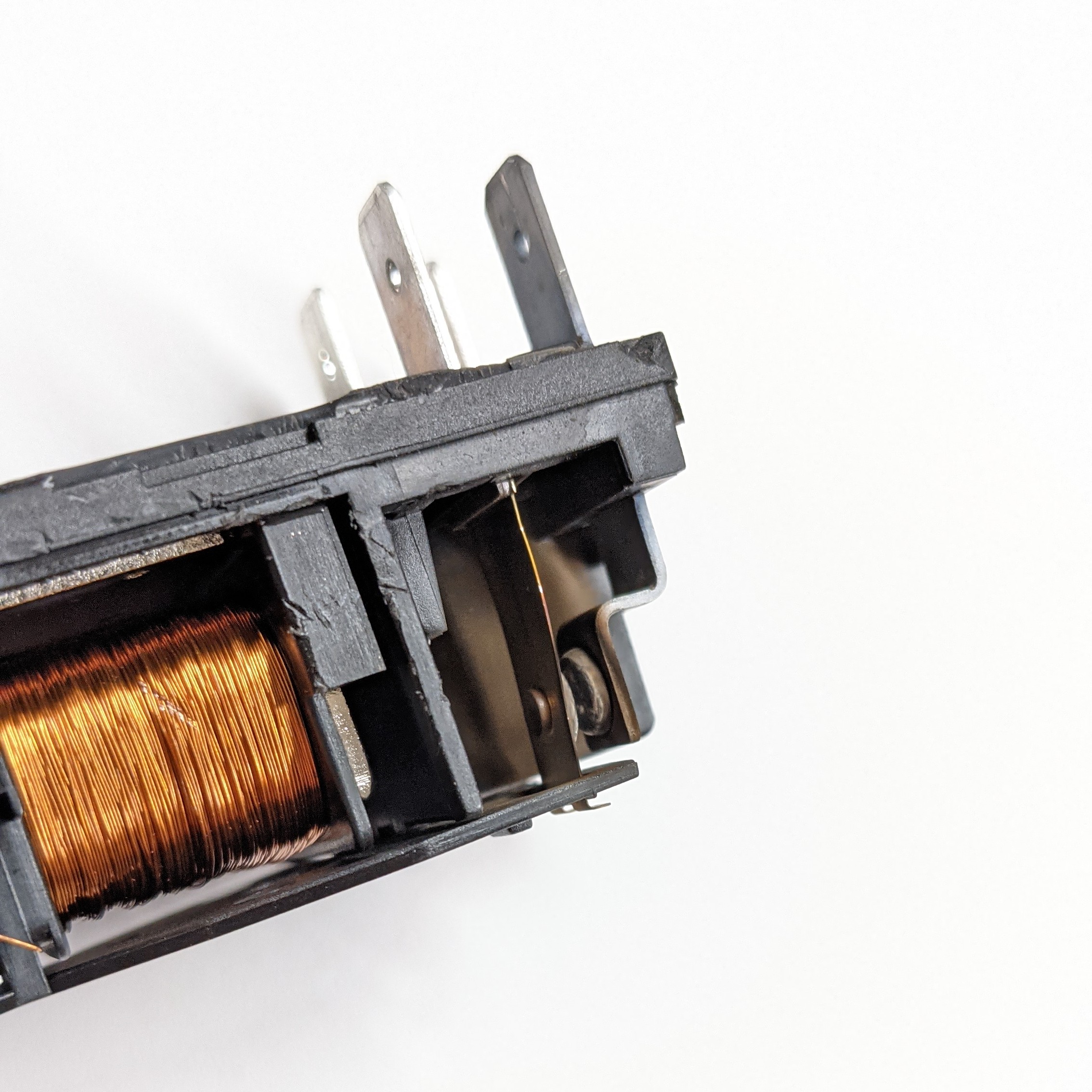
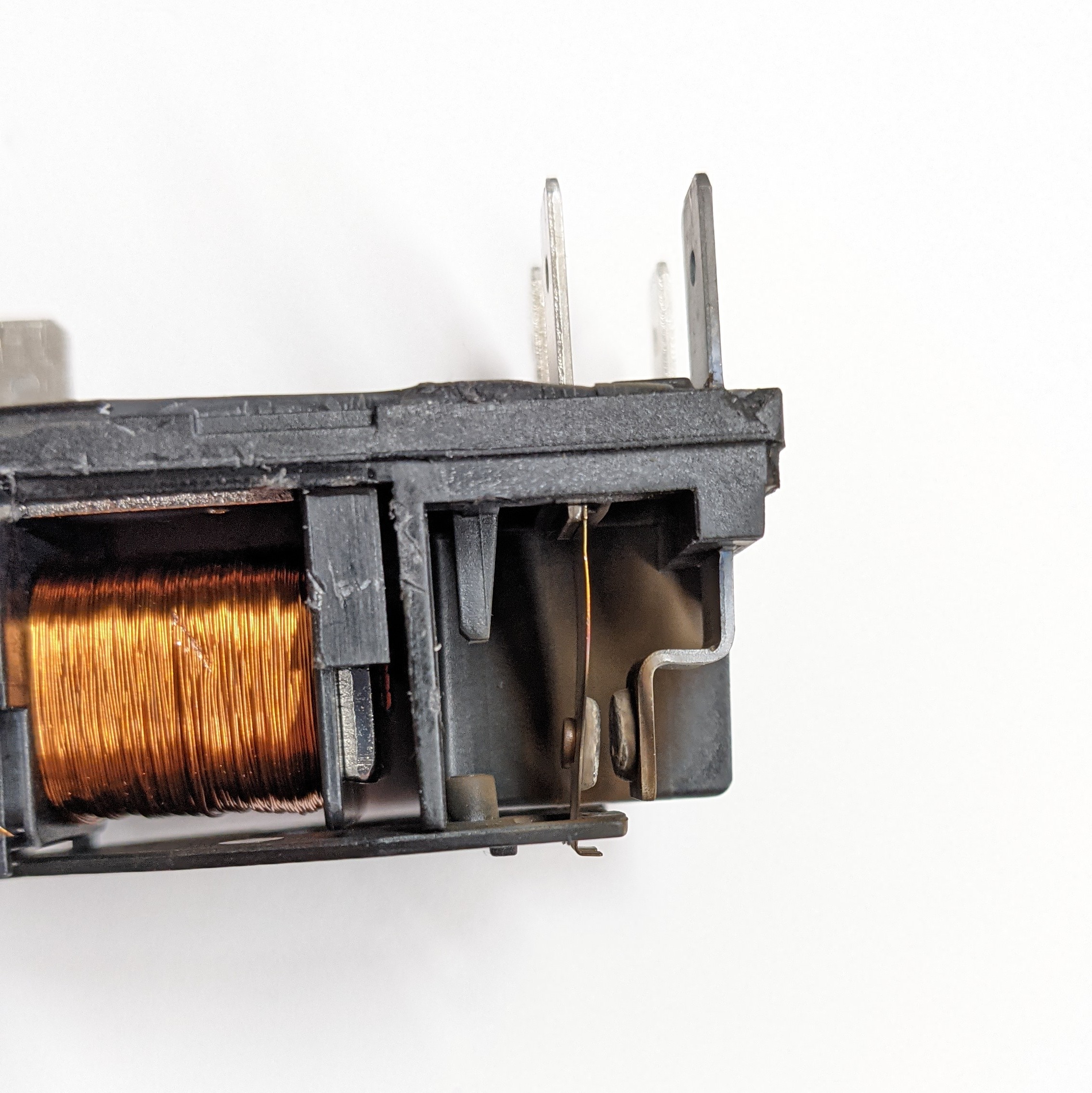
The contacts on the relay are scorched due to arcing, which seems to imply the contact is bouncing or not closing solidly? Maybe it is a problem with the voltage being applied to the coil that moves the contact?
Being old enough to remember such things (if I’m remembering correctly) , the relay contacts remind me of automobile ignition points. Arcing would cause pitting, which made peaks and craters, which would change the gap spacing over time and make things worse and worse.
The solution then was either to install new points or to use a thin file to level both contacts.
I’m not saying this is your problem, and maybe you don’t want to be bothered filing the contacts regularly. It’s just the impression I had and a suggestion to consider.
Electronic ignition is far superior to points and condensers, and perhaps another type of design would work better for you, if one is available.
There are SSR solid state relays which is a semiconductor relay, these will not pit.
One just have to check which one to get, what voltage to switch them and so on.
But when that is said, you really have to check that there is no short or anything else creating these failures.
Which in turn may solve your problem all together.
To me this relay seem quite flimsy, are you sure it is rated for the amount of current your kiln are drawing?
Regards Per-Ove
Edit to add:
You should also check that the 12v dc transformer gives stable voltage and not fluctuating, creating a “vibrating” on/off condition.
This will burn out your contacts quite fast.
In worst case they can melt the contacts together locking the elements in on position.
To me, it appears the relay is undersized for the load. You have a 10 ohm load, with 220 volts nominal, that would draw 22 Amps. Looking at the side view photo, the relay has a 20 Amp rating. It should be replaced with a 30 Amp relay as shown on the drawing.
That part escaped me.
Viewing images on a cell phone does not lend itself to clarity always.
Under normal running conditions that would be fine, but not within specs, 50% overload may go well for a time, but prolonged exposure increases risk of failure immensely.
I would tend to think that the failure from overloading, would cause more fusing the points than pitting them.
But anyway, get the proper relay and check your 12v signal from the control unit.
It says it is rated for 30A at 277VAC (20A at 400VAC), so that should be fine when running at 220VAC and 22A per the schematic.
Check the transformer for proper 24VAC output. The Sentry controller is converting the 24VAC to 12VDC for the relay. You’d have to disconnect the 12VDC connector on the relay and look at it with a multimeter when it is active to check the output voltage.
Found the solution. The female connectors we were using that plug into the relay needed to be specifically manufactured to tolerate high temps. The ones we were using were purchased at our local hardware store and could not tolerate the heat produced by the heating coils. This made them become loose fitting over time from the heat. We noticed that after a couple burnouts, the connections became loose and were able to slide right off the male prongs on the relay with zero effort.
We purchased industrial heat tolerant connectors and replaced them on all wiring that leads to the heating coils. Haven’t had a problem since.
I can’t seem to find the exact source where we bought the connectors at this time, but here’s an Amazon link with a similar (if not the same) product: High Temp Connectors. They are rated for 900 degrees and although they are sized for 12-10 gauge wire (our coil wires are 14 gauge), we found they had a more secure fit than the next size down, the 16-14 gauge connectors.
We also used electrical insulation sleeves around the connectors to prevent them from touching one another on the relay. Just as a safety measure to prevent a short circuit.
We performed this repair in December 2021. It’s currently August 2022, we just inspected them again, and everything looks just as it did when we made the original repair.